
Even a cooling breeze, a cloud passing overhead or sudden rain shower can cause roof systems to contract. If you don’t take this into account, premature roof failure could occur. Thermal expansion/contraction is responsible for most roof leaks. In the long run a properly designed weather tight roof will cost less than an improperly designed leaky low cost roof. Standing seam roof systems were designed to allow roof movement and should be specified when roof movement is expected to be a problem due to the design of the building and secondary structurals.
The Science
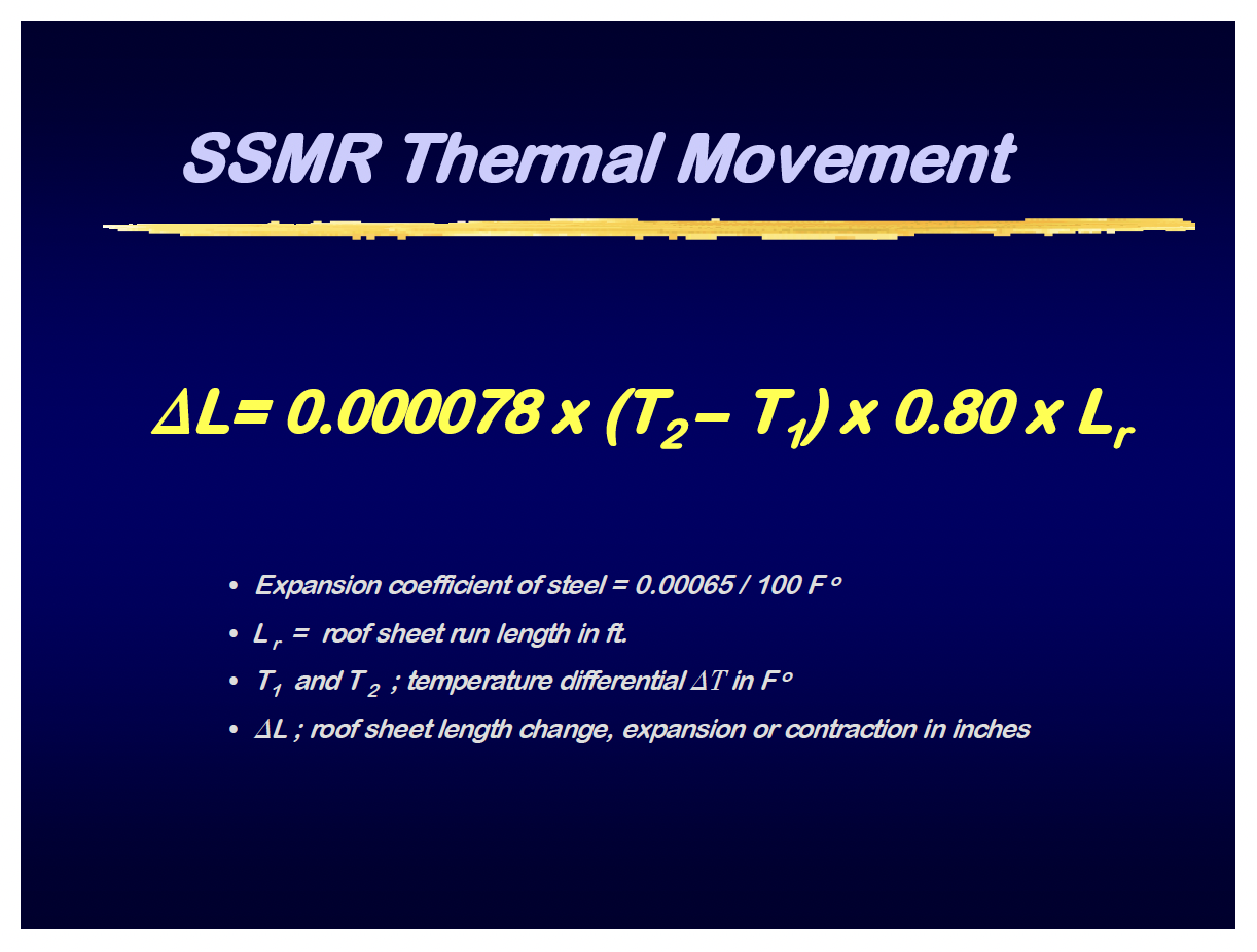
Thermal expansion occurs when heat is added to most materials, causing the material to expand. Consequently removing the heat energy (cooling) causes the material to contract. Each different material type expands at a set rate peculiar to that material for one degree in material temperature change. This rate is known as the thermal expansion coefficient for that material (see table 1).
Table 1
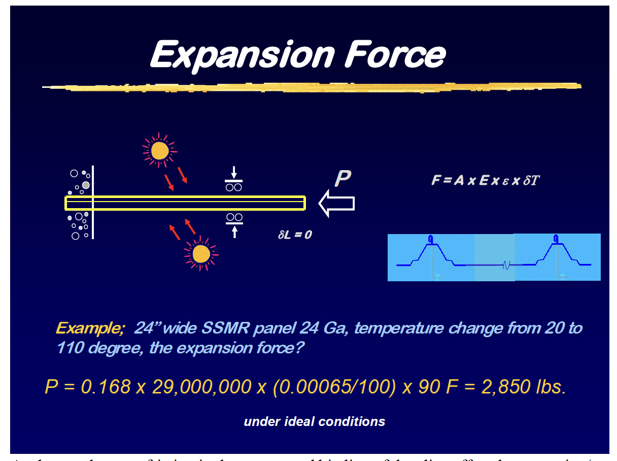
The best example of this phenomenon can be illustrated by observing a mercury bulb thermometer – for each degree of temperature change; the mercury expands a set distance inside the tube thereby indicating the temperature. Knowing these physical properties the linear expansion/contraction of an 80 feet long steel rod subjected to a 90-degree temperature change under ideal conditions can be calculated as shown in example1.
| e for 100 F˚ |
| aluminum = 0.00128 |
| steel = 0.00065 |
| concrete = 0.00099 |
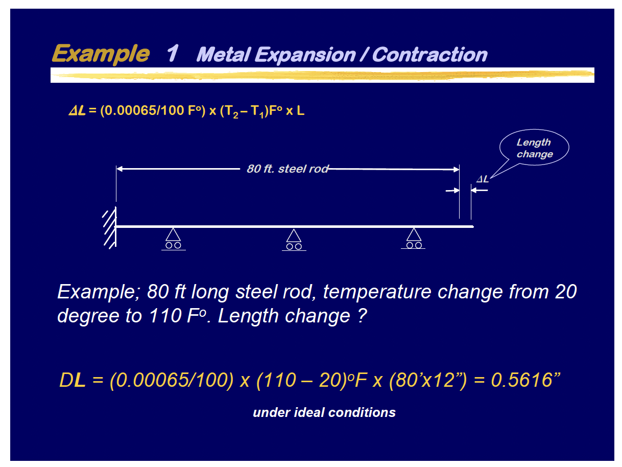
What were those ideal conditions? The steel rod was fixed at one end and free to expand without restriction on the other while being supported by frictionless roller supports, which are far from real world conditions.
A Brief History
The nature of the way we occupy the buildings under a roof will determine the amount of roof movement over the structural system. In the past, most buildings with metal roofs were used for shade and shelter or utilitarian space – meaning the temperature inside the building was nearly the same as the outside (Illustration 1).
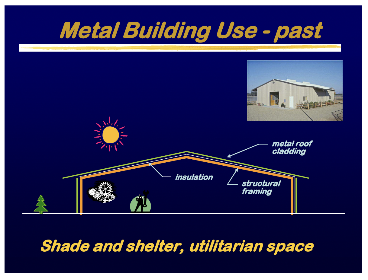
When a temperature change occurred the roof expanded/contracted at nearly the same rate as the supporting framing therefore little stress was created on the panel connections. Through fastened roofs performed reasonably well. Today’s structures are being designed for human habitat as a controlled space – meaning the temperature inside the building remains at a nearly constant temperature during the daily and seasonal temperature cycles (Illustration 2).
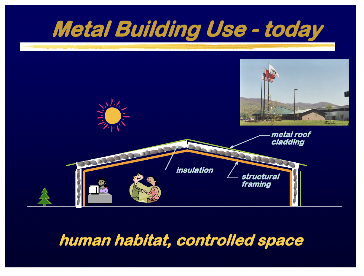
When a temperature change occurs, the roof expands/contracts while the supporting framing does at a much reduced rate since it resides inside the controlled envelope. If this differential movement is not accounted for then stress builds within the panel system and its connections. This stress will eventually compromise the integrity of the roof system if it is not allowed to move independently from the structural system.
Panel Systems
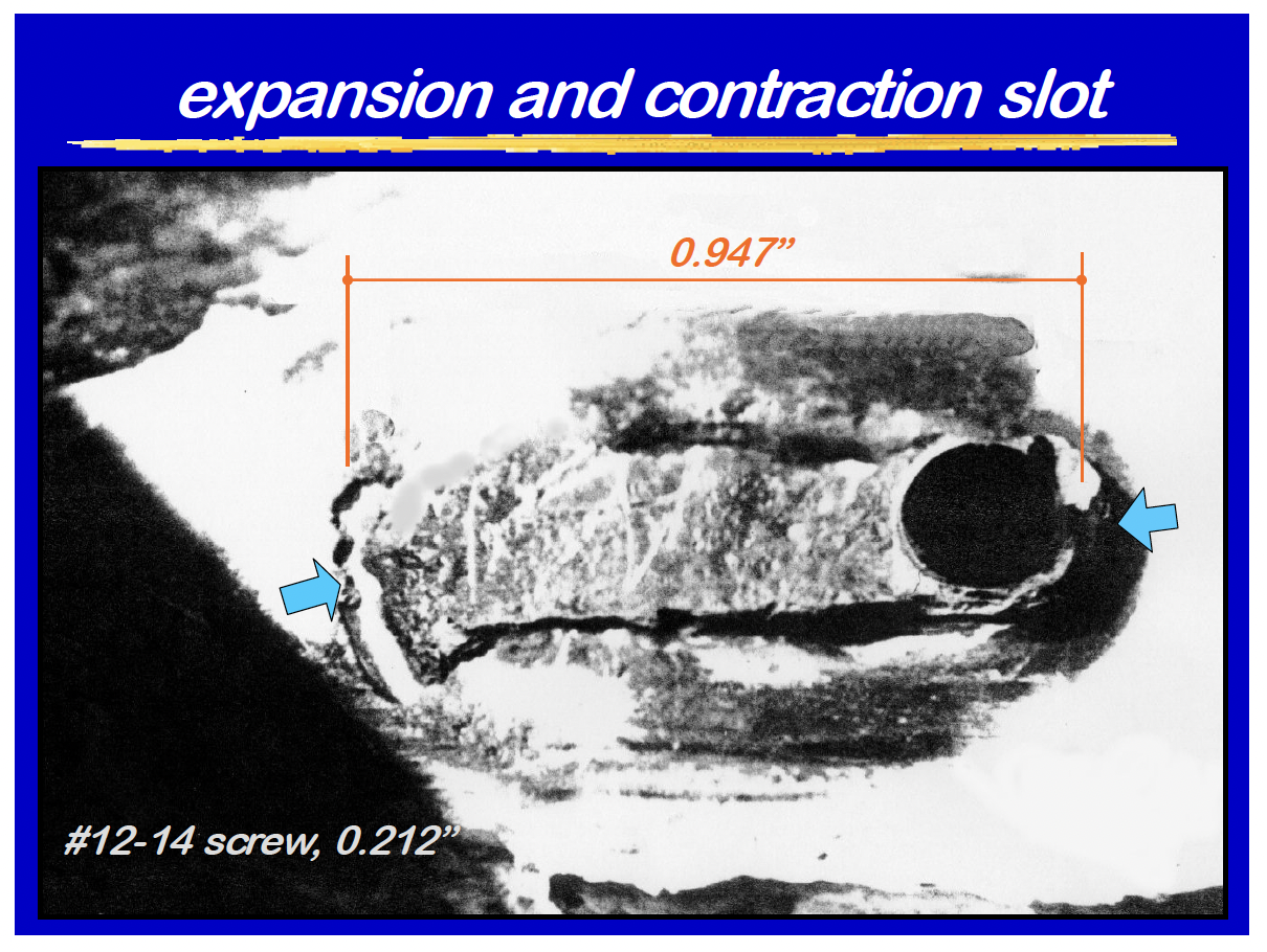
With a low cost through-fastened (screw down) system the panel is attached to the supporting structure with lines of screws that penetrate the skin in the panel pan along each purlin line. As the panel expands/contracts from eave to ridge it pushes against its connection to the purlin. The effect is cumulative and engineering studies have shown that “Z” purlins will roll in the direction of the applied force until the panel to fastener interface can no longer sustain the bearing force. The panel will slot by tearing and piling up around the screw shank (photo 1) thereby relieving the expansion/contraction stress. Once the slot grows past the sealing washer a leak has been created. Through fastened systems can be used where the roof planes a relatively short with out problems.
With a standing seam system the roof movement is allowed from eave to ridge. There are many proprietary designs but all standing seam roofs float above the supporting structure as a steel membrane via clips. These clips are attached to the panels by tabs that are seamed into the panel seams the tabs are attached to a base that allows the tab to move independent of the base, the base is fastened to the supporting structure with screws. This permits the system to be attached to the structure but still allowing the roof to move with expansion and contraction. Two piece sliding clips come in many proprietary designs but function by attaching a base to the supporting structure and a tab slides along the connection to the base Good clip design should determine clip tab fixity in the panel seam and then ensure that the force to slide the tab in the clip base is less than the clip fixity. The expansion/contraction is limited by the amount of slide designed into the clip and can be as long as 12” such as those designed by Building Research Systems. The clip should have a centering device to allow equal travel in both directions thus allowing a roof system installed in the summer at maximum expansion to fully contract and a roof system installed at maximum contraction in the winter to fully expand. The other benefit of this system is that there are no through fasteners required to attach the roof to the structure. Less through fasteners means there is a lower probability for leaks. Fortunately the panel acts as an accordion at each individual seam as expansion/contraction takes place from end wall to end wall.
There are two types of clips used with standing seam roof systems, one piece fixed clips and multi pieced sliding clips. Fixed clips can be used on relatively short roof planes in much the same way as through-fastened roofs. The expansion/contraction is accommodated through purlin roll and cladding flexibility.
Real Life Field Conditions
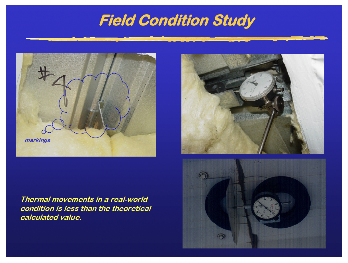
In actual field conditions, the expansion/contraction of standing seam roofs is much less than the theoretical calculated value. As a metal standing seam panel expands/contracts it can develop a considerable amount of force along the seamed rib if it is restricted from moving. This value can be calculated through the known properties of the panel as shown in the Expansion Force example.
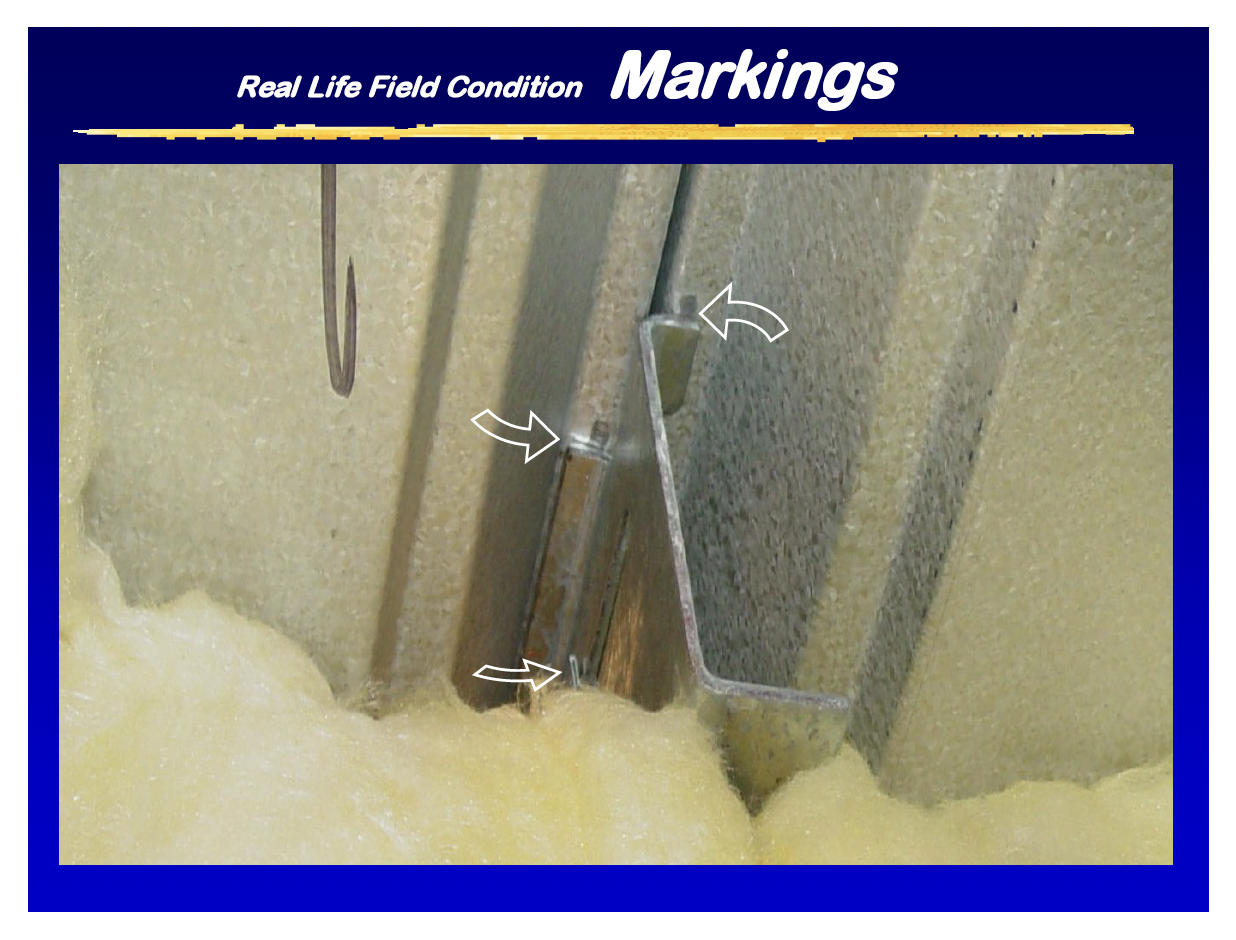
As the panel moves friction in the system and binding of the clips offset the expansion/contraction force along with cladding flexibility and purlin roll to limit the movement to less than theoretical. Field studies (photo3 & 4) have determined that for most systems this reduction can be as much as 20% below theoretical.
The adjusted formula for calculating expansion/contraction is shown in Example 3 SSMR Thermal Movement.
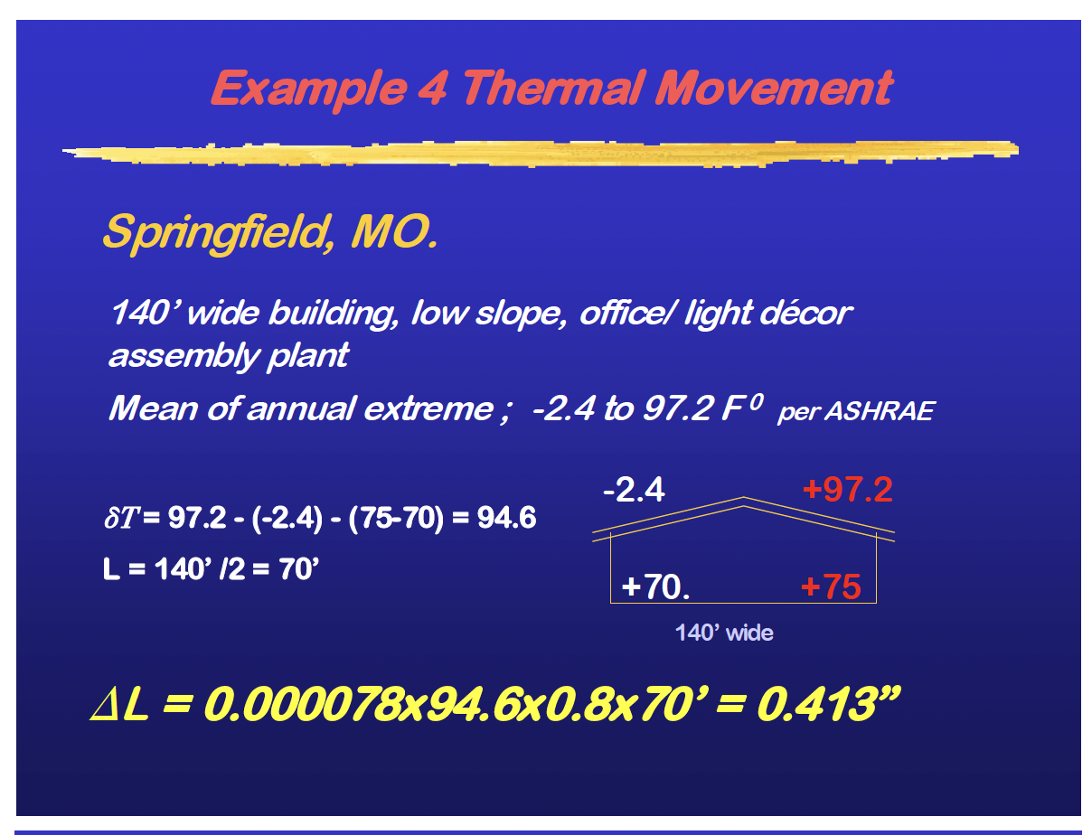
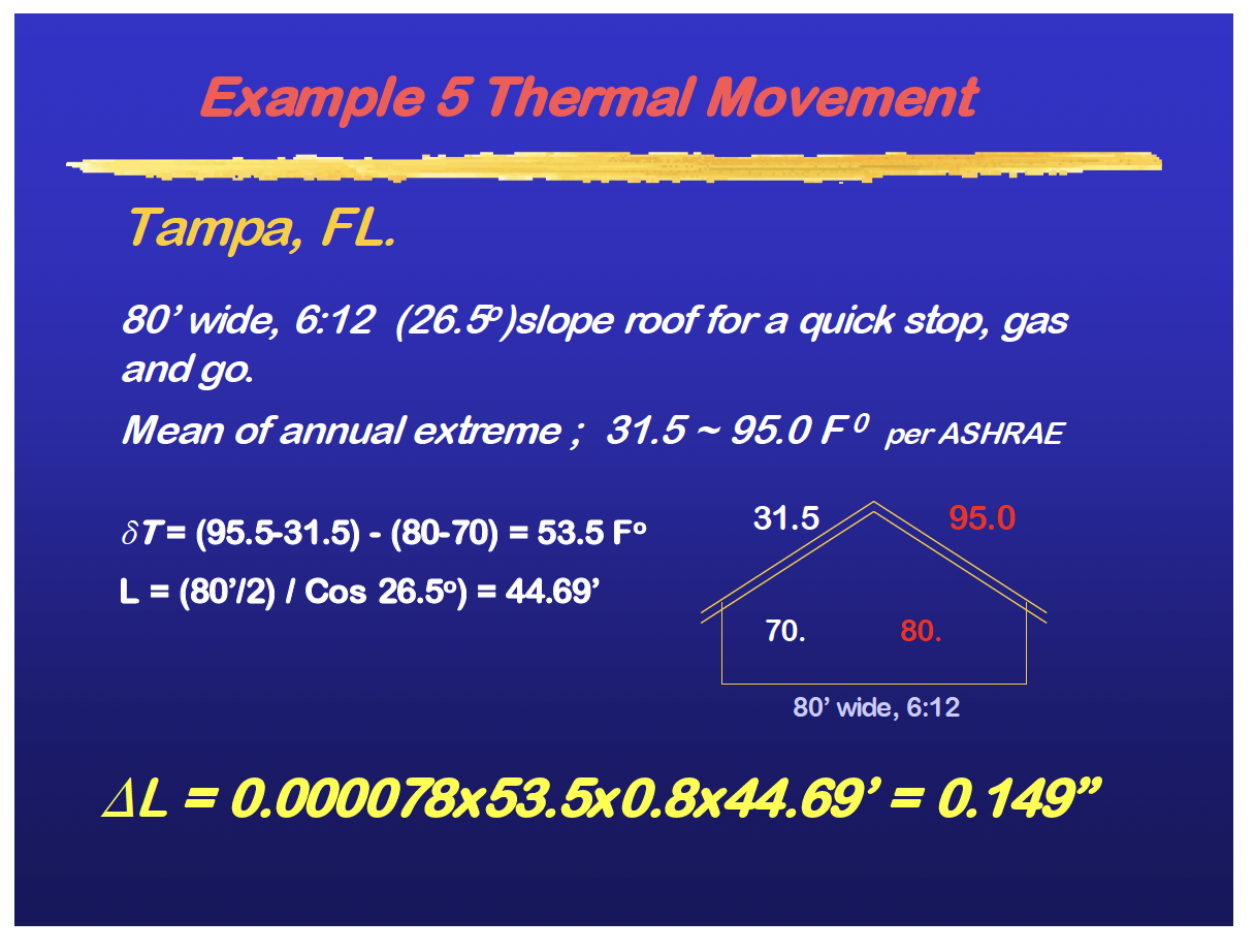
Two sample cases on how to calculate expansion for real world conditions are illustrated in the following examples. The first, Example 4 is for an office building attached to an assembly plant located in the central part of the US. The second, Example 5, is for a typical convenience store located in central Florida.
Design Recommendations on How to Control Thermal Movements
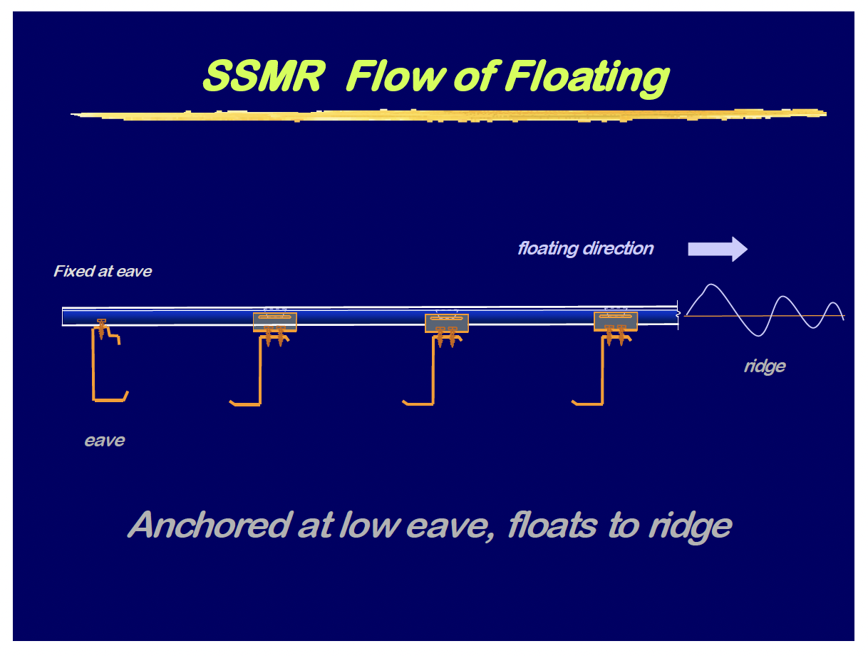
The roof system line of fixity should be at the low eave and the panels should be allowed to expand/contract to and from the ridge as shown in illustration titled SSMR Flow of Floating.
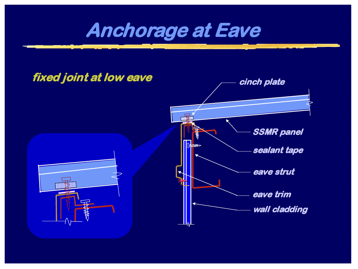
The fixed joint should provide enough fasteners with a cinch plate to resist the combined affects of gravity loads and expansion/contraction forces as shown in Anchorage at Eave. The cinch plate confines the panel material which helps to increase its bearing resistance against the fastener and compresses the sealant for a tight seal.
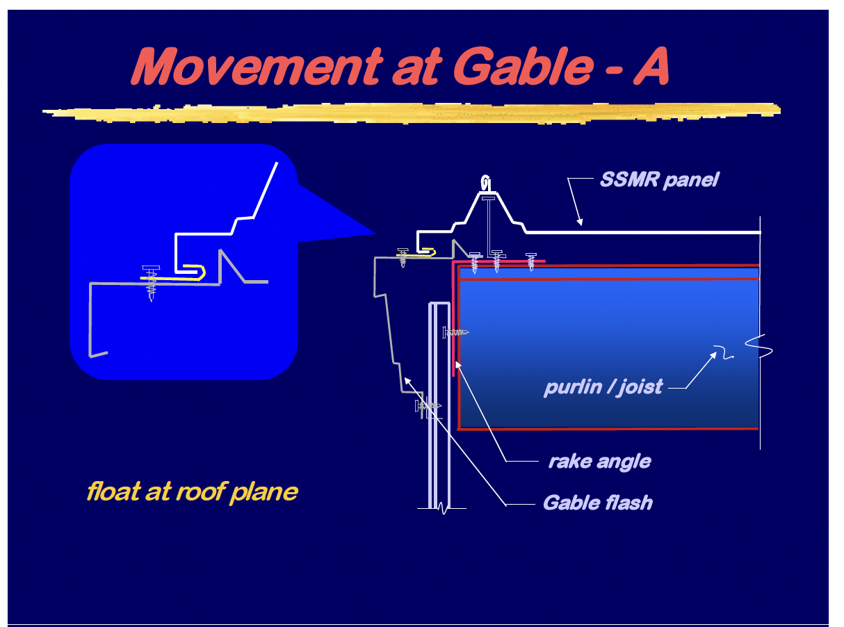
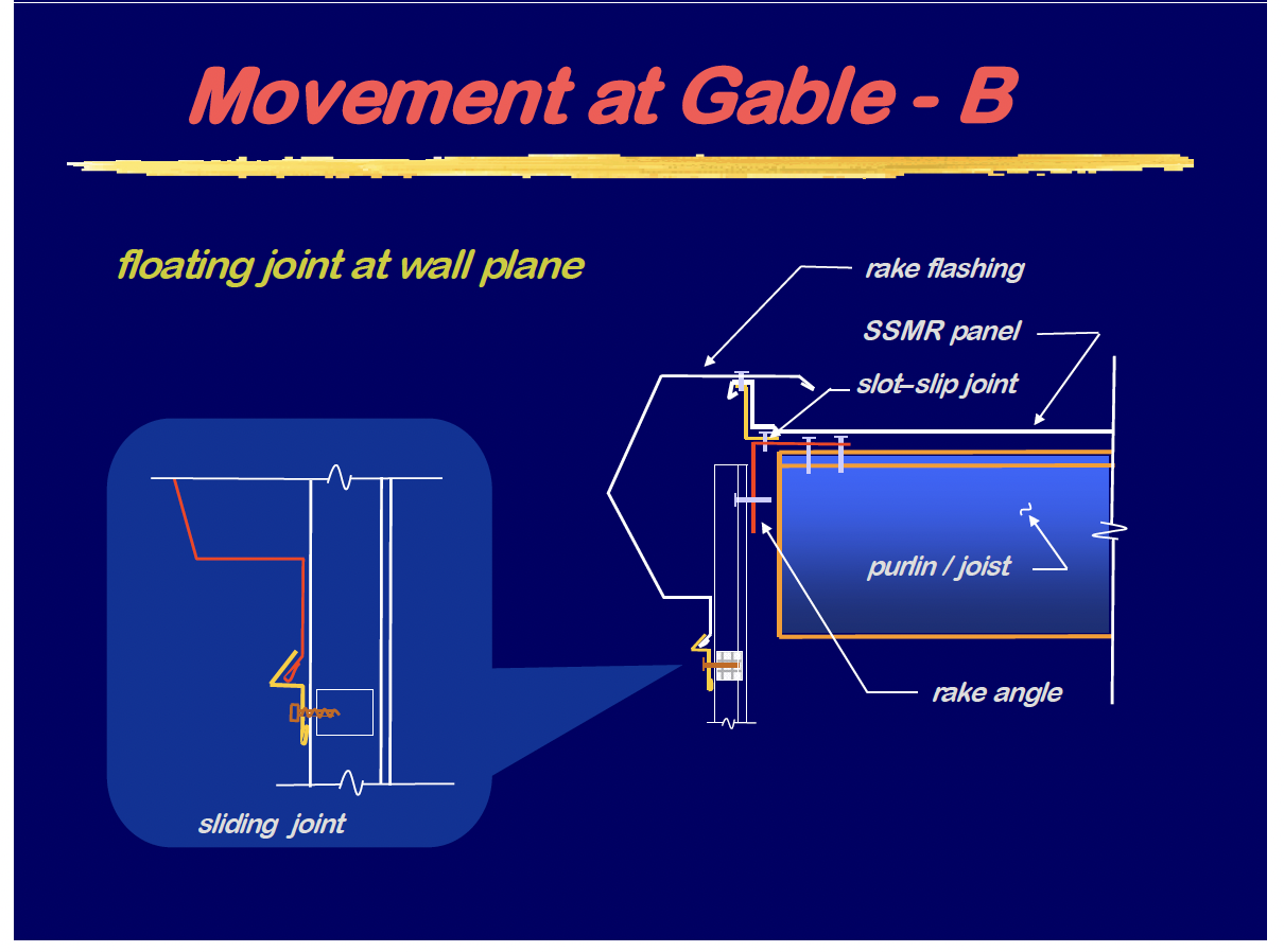
The roof system movement at the gable ends of the roof plane can accomplished by one of two methods. The gable trim can be fixed to the supporting structure and the roof float over it via clip attachment as shown in Movement at Gable- A or the gable trim can be affixed to and float with the roof system an be attached to the wall via clips as shown in Movement at Gable- B.
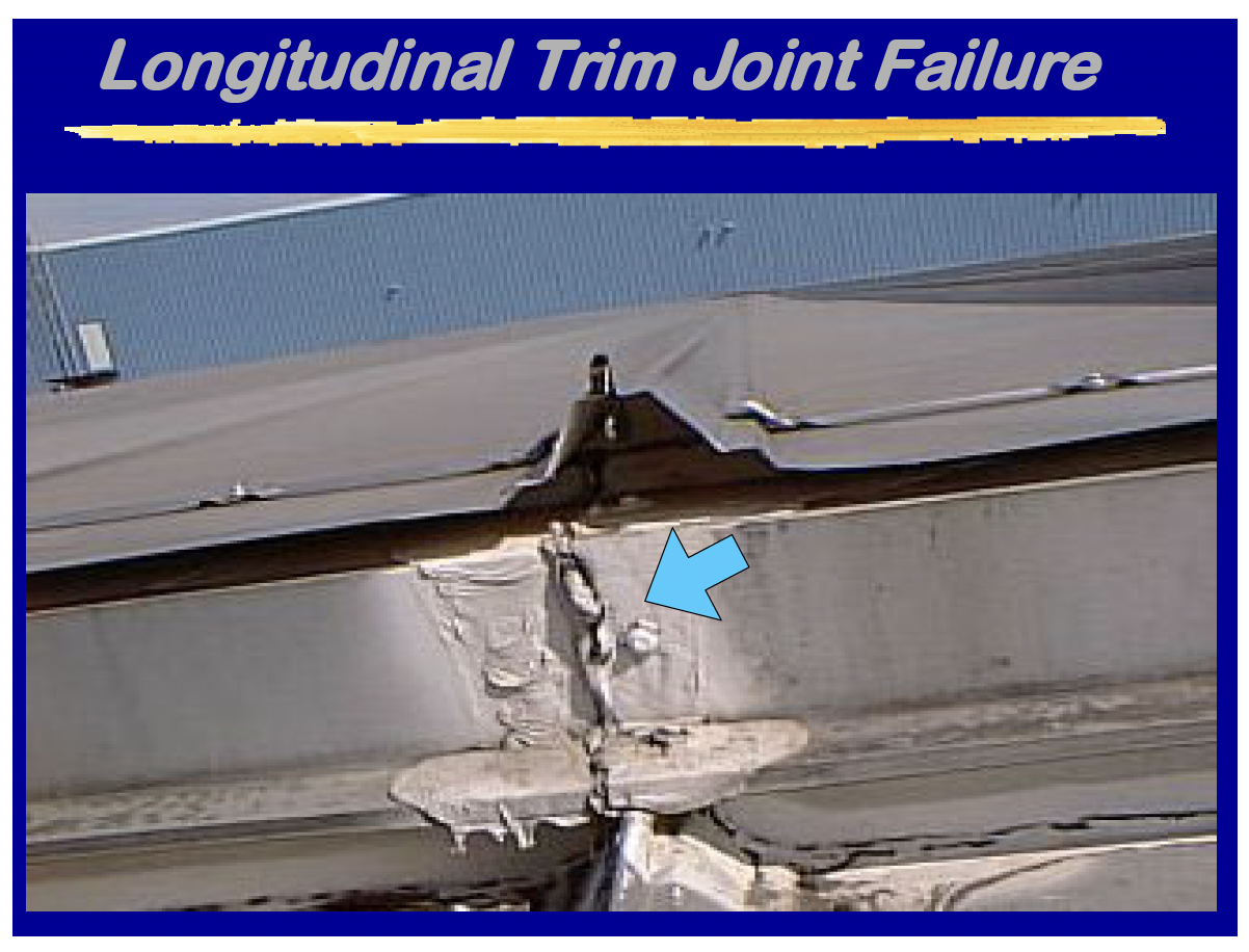
Eave trim and gutters or any other continuous longitudinal trim should be detailed for expansion/contraction even though the roof panels do not require it. The photo titled Longitudinal Trim Joint Failure shows what can happen when this minor detail is over looked. If the structural system is long enough to require and expansion joint the panel should also include an expansion joint at that location due to the concentrated movement between the two supporting structural systems.
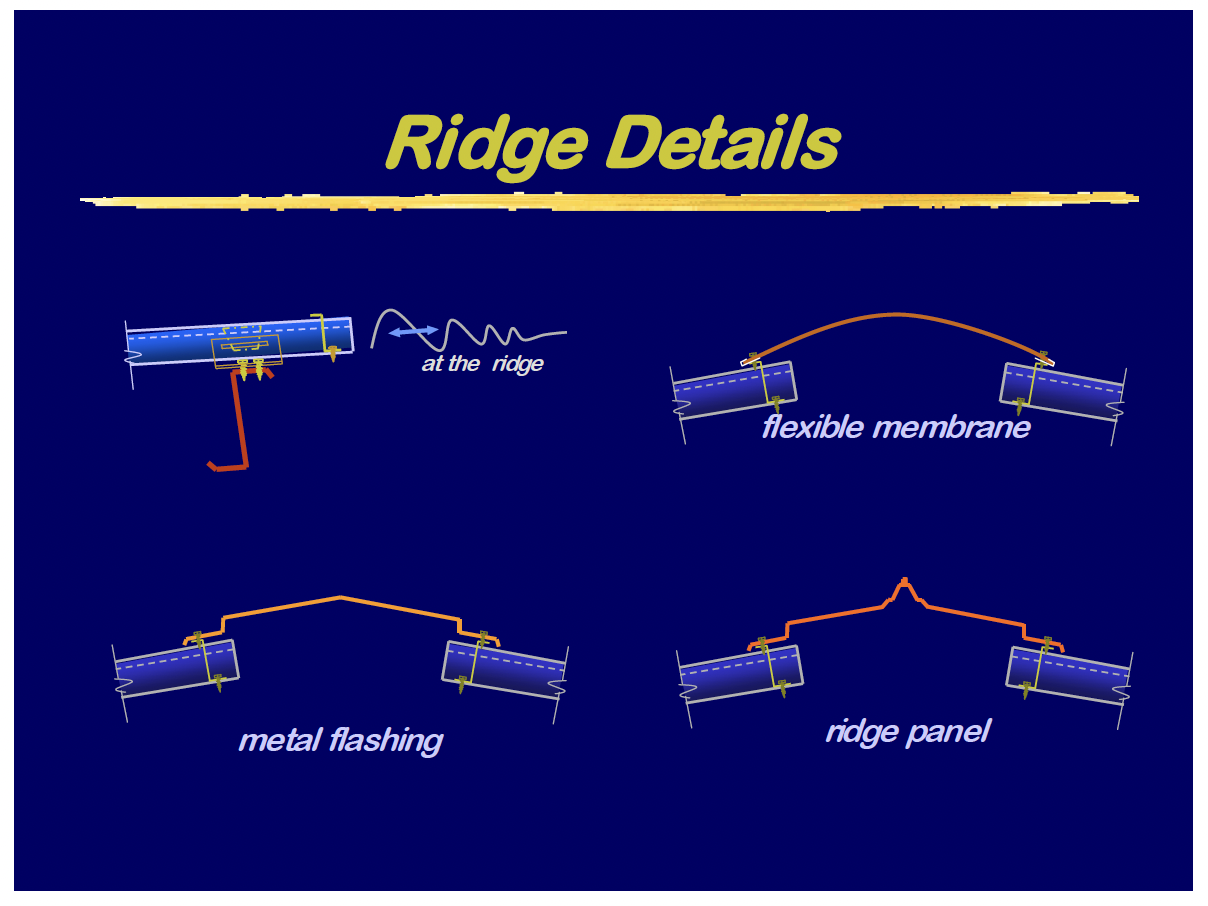
Ridge covers should be designed to flex as the roof planes move together and away with expansion and contraction as shown in Ridge details. The force to disengage the ridge connection to the end dams and the end dam fixity to the panel should be examined to be sure the system can accommodate the forces encountered with panel movement in both directions.
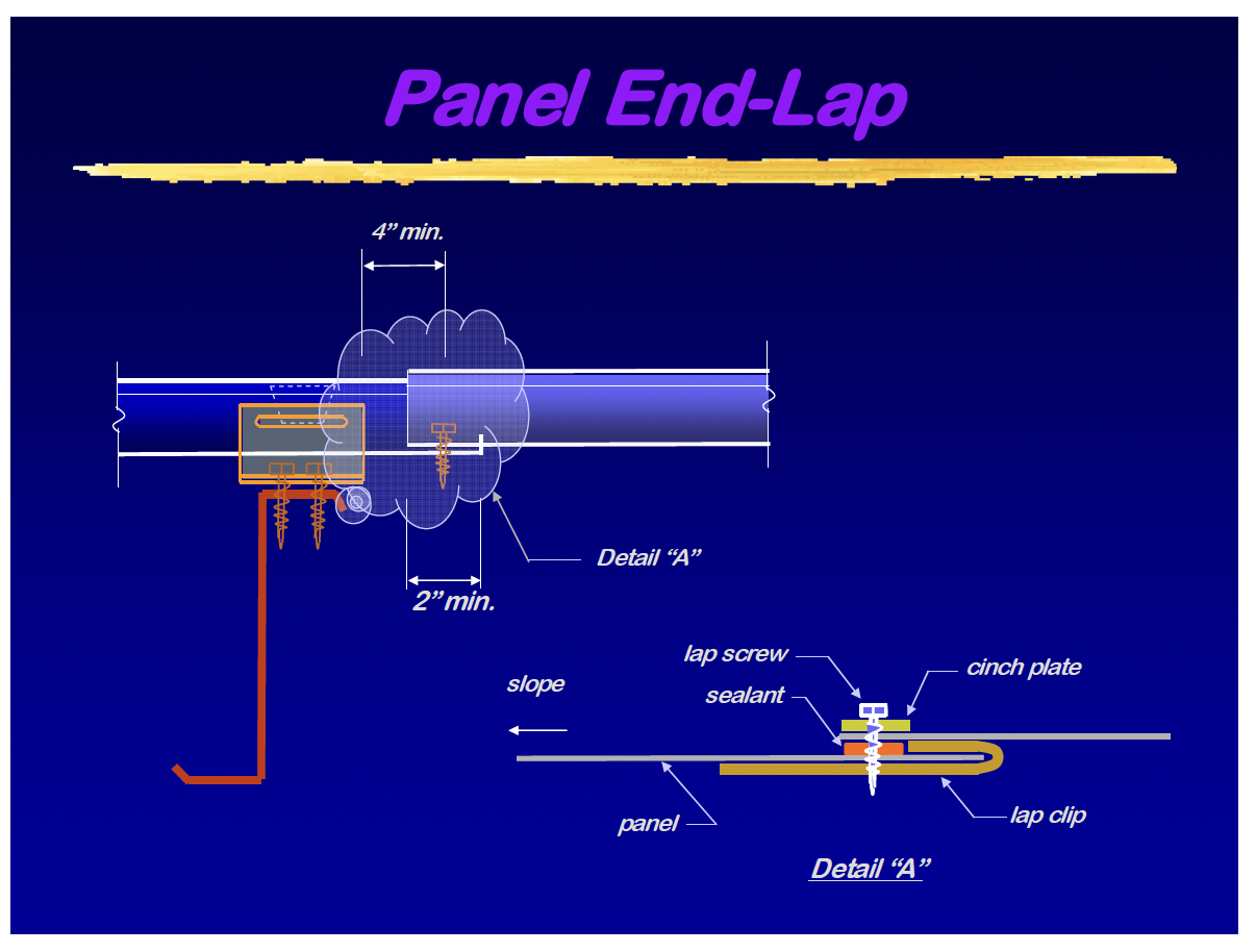
Proper panel end laps are critical in the success of wide floating roof s remaining weather tight. The end lap detail should be at least 2 inches long, provide enough room for the tape sealant to reside between the panels, have a heavy gauge back up plate and a quality cinch plate to tie it all together as illustrated. There needs to be enough screws in the end lap to pass the expansion forces from one panel to the other without the joint buckling or the fasteners failing.
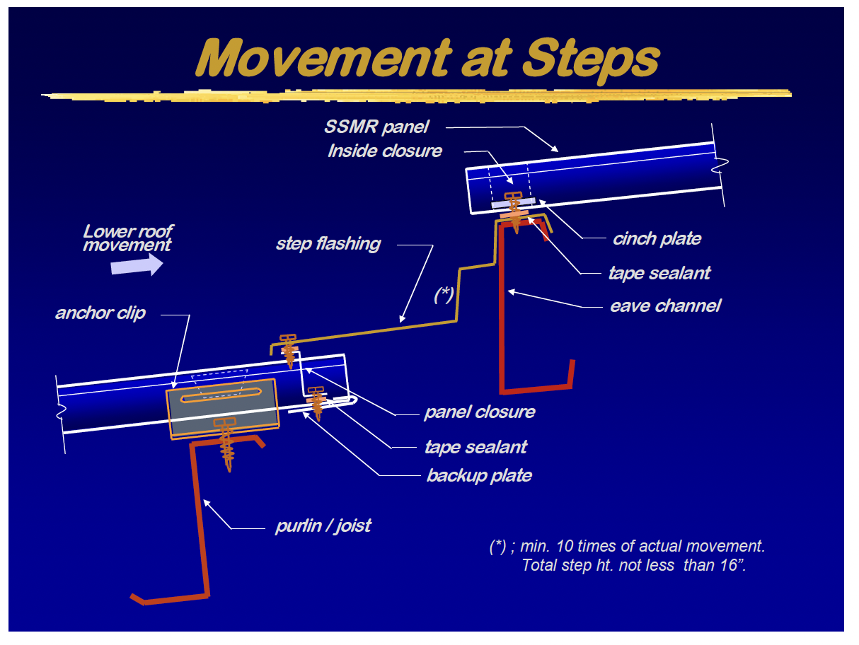
When roof planes are too wide for the available slide built into the panel clip itself then a roof step can be provided. The expansion/contraction movement is taken up in the flash and the upper roof starts the process anew.
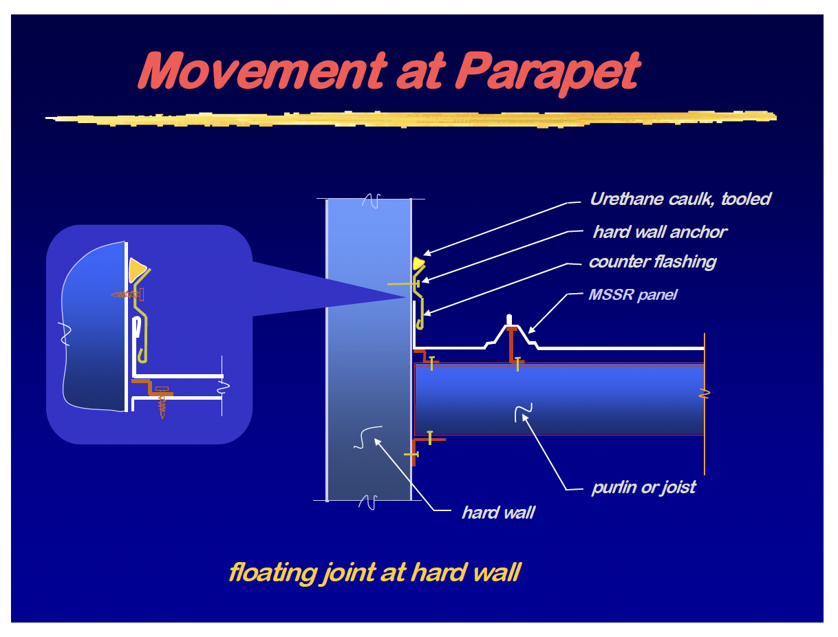
Roof planes terminating against parapets or end wall steps are allowed to move by breaking the panel pan up into a weather tight leg and sealing with a counter flash. At hard wall parapets care should be taken to properly seal the counter flash to the wall material with a high grade urethane caulk.
Reentrant corners at building width changes can cause major problems when the difference in width becomes too great. The panel on the wider roof plane is expanding/contracting while the panel at the narrower roof plane is fixed and not moving in relation to the wider roof plane. The panels can buckle, tear or break the point of fixity loose at this juncture if the forces are too great.
Large openings in the roof for service equipment should be accommodated with a floating roof curb. The curb should be able to slide on sub-framing as the roof system expands and contracts. When equipment loads or size requires a fixed curb for support a non-load bearing curb should surround the fixed curb and float with the roof system and be sealed to the fixed curb with flashing. Care should be taken to provide adequate room between the curbs at the uphill and down hill sides for the movement.
Pipe penetrations should have a large enough hole cut through the panel pan (never cut the rib) to allow for expansion/contraction. Rubber cone boots then should encompass the pipe and be able to fully cover the hole and flex with the panel movement.
Conclusion
- Thermal movement is a force of nature, it happens continuously everyday and is the major source of roof leaks.
- Designers must learn how to accommodate the thermal movement and the forces involved.
- As we do, a standing seam roof will last a long time with a trouble free service life.
KWON S. KIM, P.E.
Kwon is president of Inchon Engineering, PLLC. He has been with major metal building systems manufacturers for 40 years.
Throughout his tenure with the industry, Kwon has developed and successfully commercialized numerous roof systems and building components.
Kwon is a registered professional engineer in 39 states and holds six U.S. patents. He is a member of ASTM, AWS, ASHRAE, SPE, and UL STP 580. He has served on many committees, including two terms as Chairperson of the Fire Protection and Insurance committee for MBMA.
Richard G. Starks, JR P.E.
Richard is the Manager of Product Development for Building Research Systems, which develops, and licenses standing seam roof systems, clips and accessories. He has been involved with metal building roof systems for over ten years and developed a mini-storage system for a major metal building system manufacturer while working in their product development department. He is a member of OSEA, ASCE and serves on the MBMA Technical and Energy committees.